
1954 Buick Instrument Panel Introduction – Series 50-70
1954 BUICK INSTRUMENT PANEL INTRODUCTION: (Series 50-70) Fig. 26. The instrument panel on Series 50-70 is completely new. The panel is fabricated in two sections and both are bolted to the body. The top panel section is fastened by screws to the vertical panel, called the trim finishing panel, which supports the instruments. The trim finishing panel on 76R, 76C, and 72R Custom Styles has an “engine turn” design with a clear synthetic coating. All 50 Series and 72R Standard Styles have a painted trim finishing panel.
INSTRUMENTS: (Series 50-70) The instruments in Series 50-70 are new with the long rectangular speedometer mounted above the temperature gauge, charge indicator, oil pressure gauge, and fuel gauge. Each instrument is individually mounted in position.
SPEEDOMETER: With exception of the speedometer, the instruments may be removed and re placed from below the instrument panel. The speedometer is removed from the front of the panel by the following procedure:
NOTE: Before performing service operations on electrical units or instruments the ground battery strap should be disconnected.
- Snap out the clips below and on each side of the speedometer and pull the directional lights from the opening in the panel.
- Remove the two long hex nuts, one on each end, which hold the speedometer to the brackets.
- Pull speedometer forward from the panel until the speedometer cable can be disconnected and also remove the light bulb holders from the back of the speedometer if this has not already been done from underneath.
- Remove assembly from instrument panel. Reverse the above procedure for installation being certain to connect speedometer cable prior to positioning unit in instrument panel.
If only the speedometer cable requires service, there are two methods of removing the cable. The speedometer may be removed as previously described or the temperature gauge may be lowered to gain access to the speedometer cable housing nut.
LIGHT SWITCH: The light switch is mounted to the left and slightly above the steering column. The switch is a two position pull switch and may be re moved by pulling the rod to the full outward position, depressing the spring loaded plunger on the left side of the switch frame under the instrument panel, and pulling the rod and knob from the switch. Then using 1953 tool, J-1589, remove the retaining nut and switch.
IGNITION SWITCH: The ignition switch is un changed, however, a light has been added to the switch for easier location in the dark. The light is turned on by pulling the main light switch out to the first position.
The switch removal and replacement procedure will require removal of the ventilator bracket assembly nearest the switch to provide working clearance. Other procedures are the same.

1954 Buick Instrument Panel Introduction – Series 40-60
SERIES 40-60: The Series 40-60 Instrument Panel is of two piece construction, however, the lower section is welded to the body while the tipper section is attached by screws and is removable. The instruments are similar to 1953 Series 40 and may be removed from under the instrument panel. The light switch and ignition switch are removed in the same manner as previously described for 50-70 Series.
HEATER, DEFROSTER AND VENTILATION CONTROLS – OPERATION & ADJUSTMENTS:
(All Series) The auxiliary heater, defroster, shroud ventilation system and underseat heater are con trolled by three knobs and two toggle switches located on the lower roll of the instrument panel at the right of the steering column. See Figs. 28A & 28B.
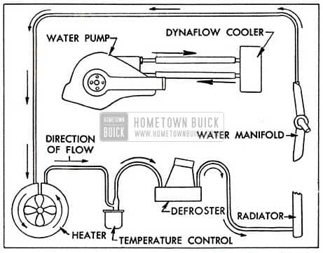
1954 Buick Water Circulation Layout
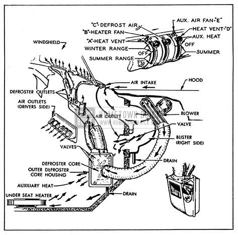
1954 Buick Heater and Ventilation System
Knob ‘A’ sets the thermostat valve and controls the left outside air ventilator. With knob ‘A’ in the center position, both the thermostat and the left ventilator are turned off. As the knob is moved upward from the center position, the temperature setting of the thermostat, which controls the quantity of water flowing through the heater and defroster cores, is increased. When the knob is moved downward from the center position, the left ventilator valve opens to admit outside air. Switch ‘B’ is a three position toggle switch which controls the speed of the underseat heater blower. lt has “off”, “low”, and “high” positions.
Knob ‘C’ controls the quantity of defroster air flowing to the windshield. The defroster air is “off” when the knob is just below the center position. As the knob is moved upward, an increasing amount of air flows to the windshield . The knob does not move below the “off” position.
Knob ‘D’ controls the quantity of air flowing from the auxiliary heater and the right ventilator. With the knob in the center position, no air flows through either the auxiliary heater or the right ventilator. As the knob is moved upward from the center position, more air flows through the auxiliary heater. When the knob is moved down from the center, the right ventilator valve opens. Switch ‘E’ is an off-on switch which controls the auxiliary heater blower.
Since the same core and blower supply both the defroster and auxiliary heat, the valves controlled by knobs ‘C’ and ‘D ‘ respectively are so arranged that as more air is supplied to the auxiliary heater, the defroster air is decreased and vice-versa. When either knob is full “on”, the other is completely closed. Naturally when ever heat is desired for the windshield defroster or auxiliary outlet, control knob “A”, which operates the thermostat, must be in the “up” position.
In cars which do not have a heater and defroster, knob ‘A’ is moved upward to open the left vent and knob ‘D’ is moved upward to open the right vent. Knob ‘C’ is always stationary and switches ‘B’ and ‘E’ are eliminated.
ADJUSTMENTS OF HEATER TEMPERATURE CONTROL
- With the control wire of lever ‘A’ clamped at the control assembly end only and the opposite end free, set the knob to the “off” position.
- Set the temperature control valve in the extreme off position (rotated clockwise until the cam locks against the roller).
- Assemble the control wire to the valve assembly and clamp in place.
When the above procedure is followed the valve will act as the stop at both ends of the lever travel thus assuring full range of temperature control.
Leave A Comment
You must be logged in to post a comment.