A new type front end suspension and steering linkage is featured on all Series. The angle of the 1954 Buick front suspension has been rotated around the centerline of the spring, thereby increasing the wheelbase without increasing frame length. This type of front suspension provides easier servicing by having the shock absorber more accessible and front end adjustment is not necessary when replacing the new type shock absorber.
FRONT SHOCK A BSORBER: The front shock absorbers are Delco double direct-acting (telescoping) hydraulic type. One shock absorber is vertically mounted in each front chassis spring. (See Fig. 16)
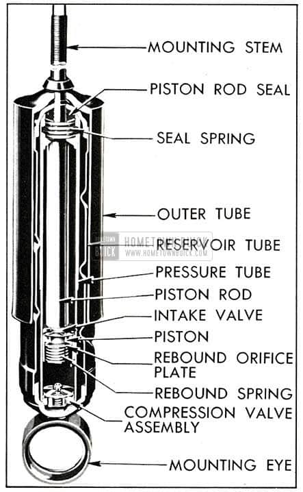
1954 Buick Front Shock Absorber
The upper end of each unit is attached by a threaded mounting stem to a bracket on the frame. The lower end is attached by a mounting eye to a bracket bolted to the lower control arm spring seat. The upper and lower attachments are insulated with rubber grommets.
Right and left front shock absorbers are identical and interchangeable, however, calibrations may differ between car models. On front shock absorbers, the part and calibration code numbers are stamped on the outer tube.
Each front shock absorber is properly filled with fluid and permanently sealed during production; therefore, no refilling or other service is possible other than replacement of deteriorated rubber grommets.
FRONT SHOCK ABSORBER CONSTRUCTION AND OPERATION: A front shock absorber consists of three concentric tubes, a piston and rod, and valves for controlling hydraulic resistance. (See Fig. 16-17)
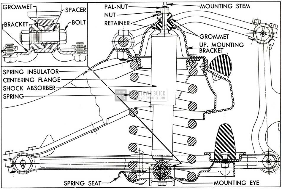
1954 Buick Front Shock Absorber Mounting
The pressure (inner) tube provides a cylinder in which the piston and rod operate. The upper end is sealed by a piston rod seal, and the lower end is closed by the compression valve assembly. This tube is completely filled with fluid at all times. The reservoir (middle) tube provides space for reserve fluid and for overflow from the pressure tube during operation. The outer tube telescopes over the reservoir tube to provide a dust shield.
The piston, piston rod and outer tube are attached by the mounting stem to the car frame, while the pressure and reservoir tubes are attached as a unit to the lower control arm spring seat through the mounting eye of the shock absorber. As the wheel moves up and down with respect to the frame, the chassis spring compresses or expands and the shock absorber is telescoped or extended. This action forces the fluid to move between the pressure and reservoir tubes through small restricting orifices in the valves. The relative slowness of fluid movement imposes restraint on the telescoping or extension of the shock absorber thus providing the required dampening effect on spring action.
COMPRESSION STROKE OPERATION: When the chassis spring is being compressed, the shock absorber is telescoped, causing the piston to move down in the pressure tube, forcing fluid through holes in the piston. The pressure lifts the intake valve plate, allowing fluid in the lower chamber to pass into the upper chamber. As the piston rod moves downward into the pressure tube it occupies space previously filled with fluid and this displaced fluid is forced out of the lower chamber into the reservoir through the restricting orifice in the compression valve. On fast or extreme movements when the fluid flow exceeds the capacity of the orifice, the spring loaded relief valve in the compression valve assembly is forced open to permit more rapid escape of fluid. The amount of compression control is governed entirely by the volume of fluid displaced by the piston rod, and the resistance to chassis spring travel is governed by the area of the orifice and the strength of the compression relief valve spring.
REBOUND STROKE OPERATION: When the chassis spring expands, or rebounds, the shock absorber is extended and its resistance is instantly effective. As the piston is pulled upward, the intake valve plate seats and fluid in the upper chamber is forced through slots in the plate and holes in the piston to build up pressure against the rebound orifice plate. As the pressure increases, the rebound spring is compressed and the orifice plate leaves its seat to permit fluid to pass into the lower chamber. As the piston rod moves upward out of the pressure tube the space previously occupied by the rod is filled with fluid drawn into the lower chamber from the reservoir. A separate intake valve in the compression valve assembly opens to permit return of this fluid.
FRONT SHOCK ABSORBER-REMOVAL AND INSTALLATION
- Hold shock absorber mounting stem with a 1/4″ end wrench while removing pal-nut and retaining nut, then remove retainer and rubber grommet.
- Remove bolts and lock washers attaching lower mounting brackets to the spring seats on the lower control arm then pull shock absorber and bracket assembly down through the opening in the spring seat.
- Clamp lower mounting bracket in vise and remove pivot bolt and nut, rubber grommet and spacer.
- Inspect all grommets and replace if not in good condition. I shock absorber operation is faulty, the unit must be replaced as it cannot be repaired.
INSTALLATION
- Make certain that the shock absorber being installed is correct for car model as indicated by code and part number stamped on outer tube.
- Install spacer and rubber grommets in mounting eye of shock absorber, install lower mounting brackets and tighten pivot bolt until brackets are tight against ends of spacer.
- Place grommet retainer and grommet on mounting stem then insert shock absorber through opening in lower control arm spring seat and pilot the mounting stem through opening in mounting bracket on frame.
- Place grommet and retainer over upper end of mounting stem, tighten retaining nut until it bottoms on shoulder of stem and install pal-nut.
- Bolt lower mounting brackets securely to lower control arm spring seats.
NOTE: Checking for proper shock absorber action while installed in car can be accomplished as in the past. The shock absorber can be checked while out of the car by mounting it vertically in a vise with safe jaws gripping the mounting eye firmly, then move the outer tube up and down by hand. There should be no uncontrolled movement in this test. A faulty shock absorber must be replaced as it cannot be disassembled for repairs.
SUPPORT UPPER ARM: The support upper arm is new in all Series. In past models the upper control arm was an integral part of the shock absorber. For 1954 the support upper arm is fastened to the top of the knuckle support on one end and the frame front cross member on the other, holding the knuckle support in proper alignment and allowing independent movement of the front suspension. The shock absorber, as previously described, is an independent unit for 1954, having no direct connection to the support upper arm.
SUPPORT UPPER ARM AND SHAFT-REMOVAL AND INSTALLATION: If a support upper arm is bent or broken, use a new arm assembly which includes the shaft, bushings, and dirt seals. lf only the shaft and bushings require replacement use the following complete procedure:
- Remove generator and engine front mounting nuts, then raise engine just enough to allow removal of support upper arm shaft bolts.
- Remove pivot pin and bushings, then remove shaft attaching bolts and remove arm assembly from car.
- Unscrew shaft bushings and remove shaft and seals from upper arm.
- Before installing any new parts, check the distance between inner ends of the upper arm. The normal dimension is 6 5/16″ plus or minus .020″
- Install a rubber seal over each end of the upper arm shaft, with the large (or bell) end of seals outward.
- Insert one end of shaft with the seal in one end of the upper arm and force the opposite end of shaft into the other end of the arm.
- Fasten the upper arm securely in a vise (close to one end to avoid springing or distortion).
- Apply a liberal amount of white lead or Lubriplate to both bushings before installation.
- Start first bushing on shaft and into upper arm at the same time. Turn bushing until head is tight against arm, then tighten to a minimum of 100 Ft. Lbs. torque.
- Center the shaft between the ends of arm and install the second bushing as in Step 9, turning shaft as required to thread into the bushing so that no binding exists.
- Before installing support upper arm and shaft assembly, turn shaft to locate the bolt holes equally distant from ends of arm, then bolt shaft securely to frame front cross member.
- Lower engine and tighten front mounting nuts. Reinstall generator.
- Reinstall upper pivot pin, bushings and seals, then check and adjust caster, camber, and toe-in.
LOWER CONTROL ARM: The lower control arm is changed in that the spring seat has provisions for mounting the lower end of the shock absorber. The service procedures for changing the lower control arm will differ only because the shock absorber and mounting bracket will have to be removed before the lower control arm can be completely disconnected from the frame.
COIL SPRINGS (FRONT): The coil front springs are unchanged except for calibrations due to frame and body changes. The service procedure in changing front springs will now include removal of front shock absorber before spring removal.
STEERING LINKAGE – ALL SERIES
A Parallelogram type of steering linkage is used on all Series for 1954 to connect both front wheels to the steering pitman arm. As shown in Fig. 18, the right and left tie rods are connected to a tubular intermediate rod.
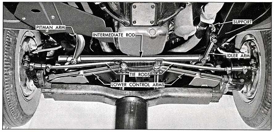
1954 Buick Steering Linkage
The left end of the intermediate rod is supported by the pitman arm and the right end is supported by an idler arm which pivots on a support attached to the frame. The pitman and idler arms are parallel with each other and move through symmetrical arcs.
Each ball stud riveted to the tie rods, pitman and idler arm, seats between pairs of ball socket type bearings contained in the intermediate rod. The bearings are held in firm contact with the ball studs through pressure applied by heavy coil springs located at the pitman and idler arm stud bearings.
Steel spacers transmit this spring pressure to the tie rod ball stud and bearings.
Flanged steel bumpers, extending through the three springs, act as spring guides, and permit a restricted movement of the ball studs and bearings as the springs absorb road shock and prevent the bearings from spreading and releasing the ball studs in the event of spring breakage. The spring tension and clearance at ends of bumpers are adjusted through the threaded end plugs.
The openings, through which the ball studs enter the intermediate rod, are protected by pressed steel dust covers to keep lubricant in and dirt and water out. Bearings and ball studs receive lubrication from in side the intermediate rod which is provided with two grease fittings.
The tie rod ends which connect the tie rods to the steering arms are basically the same as previous models with threaded sleeves and clamp bolts, and provide for toe-in adjustment.
ADJUSTMENT OF STEERING LINKAGE
The intermediate rod is maintained in position by the pitman and idler arms. This requires proper location of the idler arm on its support so that the idler arm ball stud will be approximately level with the pitman arm ball stud to insure good steering action. The support must be threaded into the idler arm bushing until the distance from the center of the support lower bolt hole to the nearest face of the idler arm is 2 21/32″ to 2 3/4″ as shown in Fig. 19.
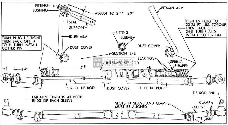
1954 Buick Steering Linkage Adjustments
After any adjustment of the idler arm on its support, the front wheels should be checked to insure proper toe-in.
IMPORTANT: If the idler arm support is dismounted from the frame for other work, such as removal of the lower crankcase, wire the support to the idler arm so that it cannot turn from its existing position and possibly change the toe-in of the front wheels.
Whenever the intermediate rod is being connected to the idler arm or pitman arm, be careful to properly seat the bearings around the ball stud and make sure that the pressed steel dust cover properly protects the opening around the ball stud. On idler arm end of rod, turn the end plug up tight then back off 1/4 to 1/2 turn (1/2 turn preferred) and install cotter pin. On the pitman arm end of the rod, tighten end plug to 20-25 Ft. Lbs. torque, then back off 1 7/8 to 2 1/2 turns and install cotter pin.
FRONT END ALIGNMENT: Procedures for front end alignment for 1954 are unchanged, however, the specifications are different due to the new steering linkage and front suspension. Front end alignment specifications for 1954 are shown on the chart Figure 20.
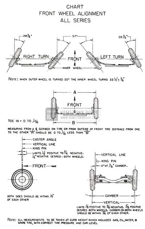
1954 Buick Front Wheel Alignment Specifications
POWER STEERING : The power steering gear assembly is basically the same except for the hydraulic valve centering spring loading which was changed due to a decrease in steering gear ratio. The loading of the springs was reduced to maintain a 4 lb. turning effort.
Leave A Comment
You must be logged in to post a comment.