There are no major 1954 Buick Engine changes in comparison to 1953. The Fireball V-8 engines used in all 1954 Series are of the same basic design differing only in bore and piston displacement, compression ratio, power, and carburetor equipment. These differences are shown by Series in the following table:
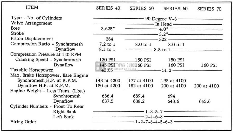
1954 Buick General Specifications
The 1954 engines, used in Series 60-50-70, (322 Cu. ln.) are basically the same as 1953 except for the following changes:
PISTON: The piston dome has been re-designed. The top of the dome has been lowered .458 inches, which is a major factor in reducing quench area and thus increasing the volume to area ratio. The cast drainage slots which were spaced around the piston at the lower edge of the oil control ring, have now been eliminated. The oil control ring for 1954 is the same design as the ring introduced as an “after- job” in 1953; otherwise the number of rings and the compression ring design are the same.
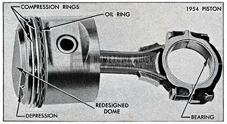
1954 Buick Piston Design
COMBUSTION CHAMBER: An. improvement for 1954 is the new combustion chamber, which has an increased volume to area ratio and gives the engine increased power and fuel economy through better thermal efficiency. Intake and exhaust ports have also been enlarged and streamlined for 1954.
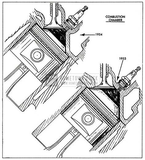
1954 Buick Combustion Chamber Design
VALVES & GUIDES: Due to the re-designed combustion chamber, the valve stems and guides have been lengthened. This is due to the combustion chamber being lowered toward the piston dome.
LOWER CRANKCASE: (Oil Pan) The oil pan has been made shallower because of a new lower overall car height. To maintain the same road clearance as 1953 , the oil pan is reduced in depth by .68 inches, and to maintain the same oil capacity a two-step pan is used. The two-step pan is also necessary to provide clearance for the intermediate rod of the steering linkage. Also, with a shallower oil pan, the oil screen housing is reduced in depth.
The removal and replacement procedure will now require disconnecting the steering idler arm bracket from the right side frame rail and lowering the steering linkage for clearance.
IMPORTANT: Idler arm bracket should be fastened in its relative position to the idler arm while disconnected from frame. This will prevent turning and possible changing of toe-in adjustment.
With exception of steering linkage, oil pan removal and replacement is the same as 1953.
IGNITION TIMING: The ignition timing mark has been relocated, and is now placed on the harmonic balancer on Series 60-50-70 and on the fan drive pulley on Series 40. The stationary timing pointer is black with yellow depressed markings, having four lines representing 0 degrees, 2.5 degrees, 5 degrees, and 7.5 degrees B.T.C. The pointer is located on the right side of the engine under the fuel pump. The revolving member (either harmonic balancer or pulley) has only one mark which is set with a timing light opposite the 5 degree (Specified) advance mark for normal conditions.
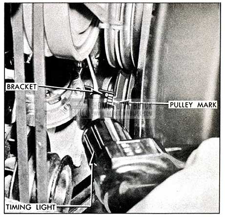
1954 Buick Engine Timing Mark
It is important to get the setting correct and care must be taken to line the 5 degree mark on the pointer with the mark on the rotating member.
In the event that a 1954 (Series 60-50-70) block assembly is installed in a 1953 chassis, the timing mark will have to be relocated on the harmonic balancer or a 1954 harmonic balancer will have to be installed along with the timing pointer on the front of the engine. The pointer and balancer for 1954 will be available through the Parts Department.
SPARK PLUG COVERS: The spark plug covers are changed due to the routing of the secondary high tension wires. The wires enter through the top rear of the covers and the cylinder number for each wire is clearly stamped in the cover for proper positioning. The width of the entry slot and the rubber grommets also provide for proper wire spacing. Ignition wire routing is shown in Figure 5.
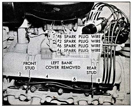
1954 Buick Spark Plug Wire Sequence
FLYWHEEL: The flywheel for Series 60-50-70 is basically the same, however, with the addition of the Series 40 V -8 engine, identification is necessary because the Series 40 flywheel is not interchangeable with Series 60-50-70. The flywheel for Series 60-50-70 can be identified by two balance holes approximately 1 1/8″ diameter, located adjacent to one of the converter drain plug access holes, while the Series 40 flywheel has approximately 3/4″ diameter holes in the same location.
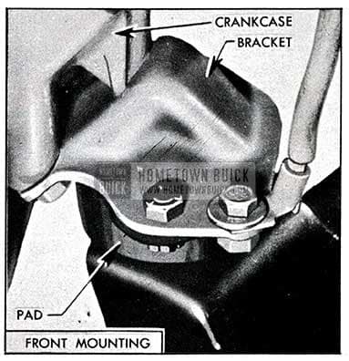
ENGINE MOUNTS: The power plant to frame mountings are the same on all Series for 1954. The front engine mounting frame brackets are welded to the frame front cross member. The transmission support and thrust mounting have been moved for ward as far as practical and now closely approach the point of minimum vibration in the power plant . All Dynaflow models have interchangeable rear mounts but not interchangeable with Synchromesh transmission.
The method of locating the engine in the frame has been changed. Holes in the frame bracket are no longer made oversize but the engine brackets have been slotted to provide fore and aft tolerances. This method prevents the improper locating of the power plant laterally in the frame.
The left front engine mount is the same as previously used, however, the right front mount has been changed to include the generator bracket. (See Fig. 6)
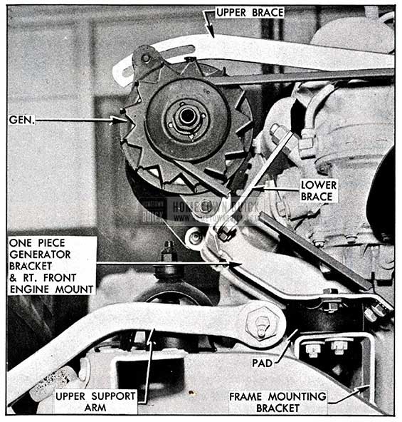
1954 Buick Front Engine Mounts
1954 Buick Front Engine Mounts View
The rear transmission and engine support has been moved foreward and attached to brackets on the frame members. IMPORTANT: If the rear trans mission support is removed for any reason, and shims are found between support and frame members, the same shims should be installed in their original position .
The rear transmission mount is secured to the rear bearing retainer. A rubber pad is located between the rear bearing retainer and support . The thrust plate is attached directly to the rear bearing retainer with a thrust pad and shims between plate and support. The shims are used to take up clearances between support and thrust plate. (See Fig. 7A&7B)
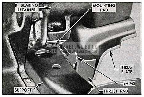
1954 Buick Rear Engine Mount – Upper View
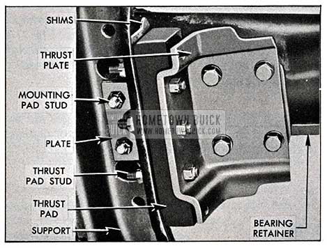
1954 Buick Rear Engine Mount- Lower View
If the thrust plate is removed for any service operation the same shims should also be returned to their original position.
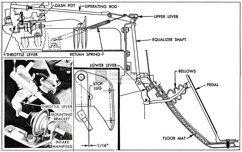
FUEL & EXHAUST: New throttle linkages are incorporated on the 1954 models because of changes in the ventilation system and body styling.
The dash pot has been relocated and the bracket is mounted on the left side of the intake manifold which positions the dash pot for direct contact with the throttle lever on the carburetor. (See Fig. 8)
1954 Buick Dash Pot Mounting
Adjustments for throttle linkage and dash pot are as follows.
- THROTTLE LINKAGE ADJUSTMENT: Prior to making any adjustments be certain the floor mat is properly positioned, the linkage up to the carburetor lubricated and free, the attaching screws, bolts etc. are properly tightened, and that the accelerator pedal can move the throttle valves smoothly from the fully closed to the wide open position. Also be sure the return spring is strong enough to fully close the throttle valve.
- With engine shut off and the throttle lever closed to hot idle position 450 RPM, check clearance between the equalizer shaft lower end and the stop lug on the shaft to cowl mounting bracket. This clearance should be approximately 1/16″. (See Fig. 8)
- If the specified clearance at closed throttle and the proper condition at wide open throttle do not exist, disconnect the throttle operating rod from the shaft upper lever and adjust as required.
- In some cases it may be necessary to remove the upper lever from the serrated end of the shaft and reinstall it in a new position.
- Hold choke valve closed and check for proper operation of choke unloader when accelerator is pressed to floor mat. If choke unloader does not operate properly, adjust as described in Paragraph 3-17 (Carter) and 3-26 (Stromberg) in the 1953 Shop Manual.
- Finally, check for smooth operation of linkage from fully closed to wide open position of throttle valve. In closed position, the throttle operating rod must be at sufficient angle to the shaft upper lever to provide positive operation of the throttle valves when accelerator pedal is first pressed.
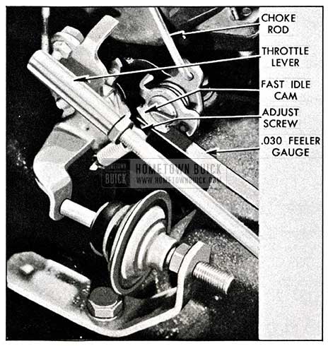
- DASH POT ADJUSTM ENT: Adjust the dash pot only after the throttle linkage has been adjusted, and engine is at normal operating temperature.
- Rotate fast idle cam to extreme cold idle (choke closed) position and hold the throttle lever closed against a .030 w feeler gauge placed between the stop screw and the highest step of the fast idle cam (See Fig. 9)
1954 Buick Preliminary Dash Pot Setting
- Adjust dash pot until it barely clears the arm of throttle lever, and tighten lock nut. This is a preliminary setting only- -be sure to continue with the following steps.
- Final setting of the dash pot should result in the engine returning to idle promptly without engine stalling. If the engine stalls when returning to idle the dash pot should be moved forward. Rearward movement of the dash pot will reduce time required to idle the engine. Always tighten lock nut after each adjustment.
- If proper control cannot be obtained by adjustment, it will be necessary to replace the dash pot.
- Rotate fast idle cam to extreme cold idle (choke closed) position and hold the throttle lever closed against a .030 w feeler gauge placed between the stop screw and the highest step of the fast idle cam (See Fig. 9)
AIR CLEANER AND SILENCER ASSEMBLIES: The air cleaner and silencer assemblies are of the same design as used on Series 50 and 70 in 1953. The new 60 Series uses the same assembly as Series 70, and the new 264 cubic inch V-8 engine on Series 40 uses the same air cleaner and silencer assembly as series 50.
The air cleaner and silencer assemblies on all Series have been lowered in height due to new body design and the hold down wing nut has been recessed lower into the top to prevent damage to hood insulation. Oil capacity remains 1 pt. of SAE-50 Engine Oil.
FUEL LINES: The fuel line from the gas tank is positioned along the left side of the frame to just forward of the cowl. The line then passes through the left frame rail, goes forward through the front frame cross member and over to the fuel pump.
SERIES 40 V-8 ENGINES: The Series 40 V-8 engines have a bore size of 3.625 inches, a stroke of3.2 inches and a piston displacement of 264 cubic inches.
The engines used with the Synchromesh transmissions are equipped with cast iron flywheels for clutch application and have a compression ratio of 7.2 to 1.
The engines used with Dynaflow transmissions are equipped with steel flywheels for torque converter application and have a compression ratio of 8.1 to 1.
Compression ratio is determined by the height of the piston dome in Series 40 engines. The higher compression engine (Dynaflow 8.1 to 1) has a piston dome height approximately .349″ above the top shoulder of the piston whereas the lower compression engine (Synchromesh 7.2 to 1).has a piston dome height of .243″, the difference being .106″.
The low compression piston can be identified by raised letters “L.C” (Low Compression) on the top shoulder of the piston on valve side.
All 40 Series engines have cylinder head gaskets .015″ thick.
An important feature for all Series engines is the interchangeability of parts. The chart, figure 10, shows the engine parts by Series which are inter changeable with each other for 1954.
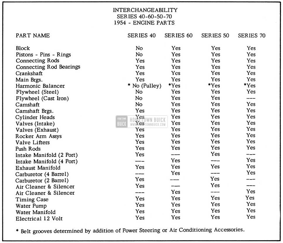
1954 Buick Engine Parts – Interchangeability
Because of the similarity in appearance of the 1954 engines, and their parts, several methods of identification have been incorporated.
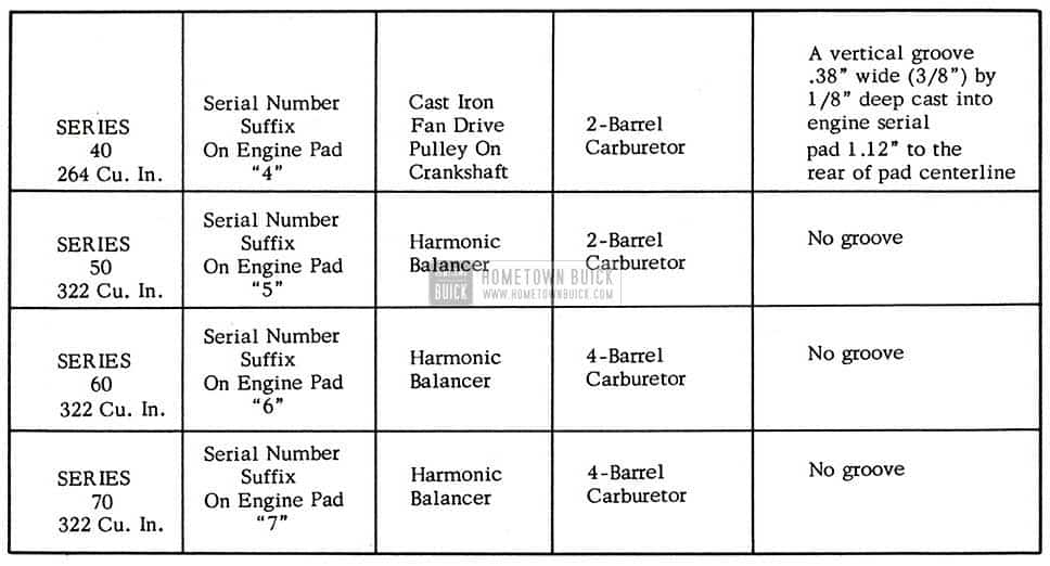
1954 Buick Engine Identification
The chart, figure11, lists the identification points for the engine by Series as they appear in the .chassis. Other identifications are as follows:
- CAMSHAFT: The camshaft forSeries40engines will have a groove .060″ wide cut into the ground land just forward of the number 3 bearing journal and the Series 60-50-70 camshaft will have a smooth land surface at this point as shown in Fig. 12.
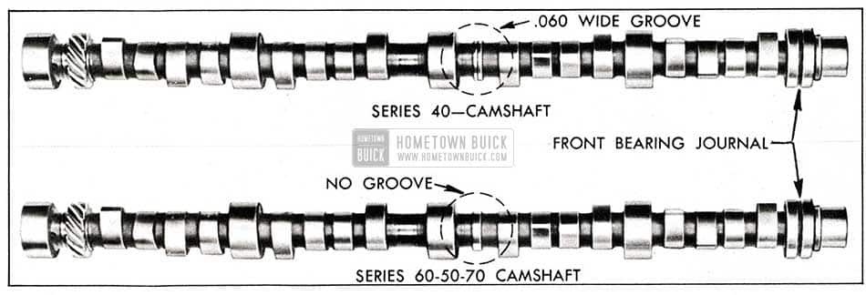
1954 Buick Cam Shaft Identification
- FLYWHEEL: The Series 40 flywheel is identified by two balance holes approximately 3/4″ in diameter, located adjacent to one of the converter drain plug holes, while the flywheel for Series 60-50 and 70 have holes approximately 1 1/8″ in diameter in the same location.
Leave A Comment
You must be logged in to post a comment.