CLUTCH (SYNCHROMESH): The 1954 Buick clutch control has been changed due to a desire for a shorter pedal to floor height for ease of operation. The pedal height is reduced 3/4″ and the linkage adjusted to compensate for the change.
The clutch assembly is the same type used in 1953 Series 40.
The clutch pedal is a two piece assembly with a clamp bolt extending through a groove in the pedal shaft which locates and secures the pedal in proper position. To provide a more effective seal against road splash and dirt, the body toe board has been re-designed to eliminate the large cut out which was necessary for the installation of the 1953 pedal.
Clutch service procedures have changed only in the removal and installation of the clutch pedal. To remove the pedal it is necessary to remove the clamp bolt which holds the pedal shaft to the lever and pull the clutch pedal through the toe board. Installation is a reverse of the removal procedure.
DYNAFLOW TRANSMISSION: The planetary gear set in the Dynaflow torque converter planetary gear teeth have been changed to an 18 1/” degree helex angle, (14 degree in 1953) the carrier pinion pin holes have been relocated, the lugs on the sun gear, which coupled the sun gear to the stator, have been removed and a sun gear yoke has been added. See Fig. 13.
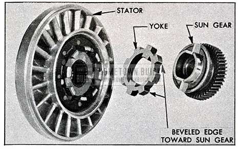
1954 Buick Sun Gear to Stator Assembly
The converter pump, turbines and stator have not been re-designed, however, the modification of the planetary gear set greatly reduces the interchange ability of converter parts between 1953 and 1954 units.
The following parts are NOT interchangeable between 1953 and 1954 Dynaflow torque converters.
1ST TURBINE DISC & HUB ASSEMBLY
2ND TURBINE
PLANET CARRIER
PLANET PINIONS
SUN GEAR
The Dynaflow service procedure remains the same except for the assembly of the sun gear to the stator.
The sun gear yoke (See Fig. 13) is a new part which couples the sun gear to the stator. The yoke is assembled to the sun gear and the 45 degree chamfered outer diameter will be facing the sun gear. The sun gear and yoke are then assembled to the stator in the usual manner.
REAR BEARING RETAINER: The rear bearing retainers on all Series have been modified or changed due to changes in frame mountings or as in the case of the 40 Series, due to a new V-8 engine.
The rear transmission (engine) support and thrust plate relocation has been previously discussed under ENGINE MOUNTS.
The rear bearing retainer on Series 40 has been re-designed and lengthened approximately 4 13/16 inches due to the new V-8 engine and frame. The planet carrier has also been lengthened for the same reason. The same rear bearing retainer and planet carrier assembly is used on the Series 40 and 60 models.
UNIVERSAL JOINT: A hole extends through the torque tube flange and into the torque ball retainer . A suitable punch may be inserted into this hole to maintain proper alignment during assembly.
REAR AXLE ASSEMBLY: The differential assembly on Series 40 and 60 is the same as the assembly introduced as an “after-job” on the 1953 Series 40, Series 50 and 70 remain the same as 1953.
Tubular strut rods, similar to the 1953 Series 40, modified for under-body clearance, are used on all Series for improved rigidity of the axle.
The rear axle ratios for 1954 used with Synchromesh or Dynaflow transmissions with no optional ratio available, other than for export, are listed on the following table, Figure 14.
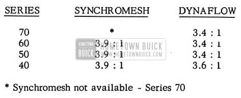
1954 Buick Rear Axle Ratios
The following table lists the proper speedometer worm and pinions to use along with rear axle ratios on 1954 models.
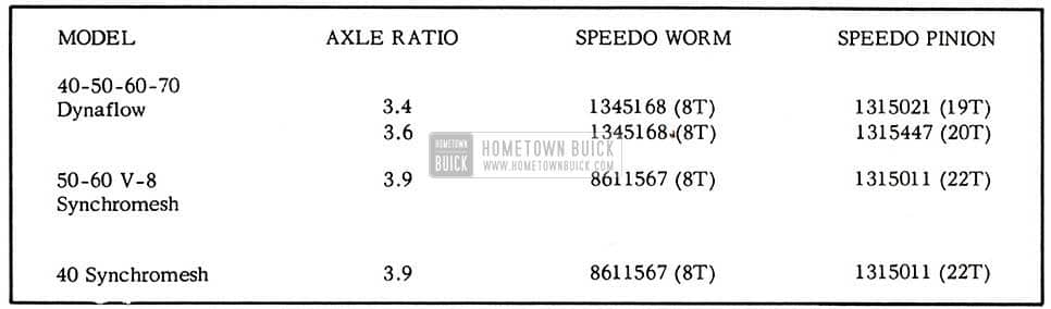
1954 Buick Proper Speedometer Worm and Pinions
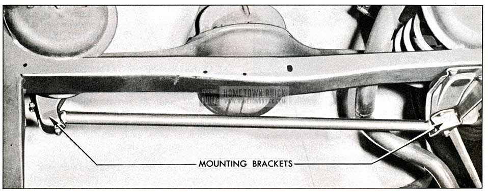
TRANSVERSE RA DIUS ROD: A new type transverse radius rod is used on the 1954 Series 40, 50, 60, and 70. This rod differs in that the bushing eyes are set at an angle to the axis of the rod rather than square as in previous models. See Figure 15A & 15B.
1954 Buick Radius Rod -Top View

1954 Buick Radius Rod – Rear View
This places the bushings in line with the true axis of axle motion (a line from torque ball to radius rod frame pin), instead of about an axis parallel to the center line of the car.
The new radius rod, interchangeable between Series 40-60 and 50-70, are of the same design, but differ in that the radius rod for the Series 50-70 is longer, due to wider rear tread.
The right side of the transverse radius rod is fastened to a bracket on the car frame while the left side is connected to the axle.
The removal and installation of the transverse radius rod is basically the same as in the past. Four bolts on the right side bracket and two from the left side bracket, plus the two large hex nuts from the pins will disconnect the radius rod so it can be removed. The pins will remain in place on the inner part of the bracket when the rod and outer part of the bracket are separated during disassembly.
REAR SHOCK ABSORBERS: The rear shock absorbers on all Series are the same double acting shock absorbers used in 1953 with changes made in calibrations to compensate for other changes in the body and chassis. Service procedures are unchanged.
Leave A Comment
You must be logged in to post a comment.