
1954 Buick Air Conditioning Unit
The 1954 Buick air conditioning unit as adapted to 1954 production has considerable changes and modifications.
- The changes are as follows:
- Check Valve.
The check valve as used in 1953, has been deleted. No valve is being used.
- The receiver continues to be located beneath the radiator pan, however, its shut off valve has been deleted.
- Sight Glass.
The sight glass has been conveniently located in the engine compartment along the front edge of the right fender skirt.
- By-Pass Solenoid Valve.
The by -pass solenoid valve has been relocated to a position just beneath the right hood operating spring.
- Evaporator and Housing.
The evaporator and housing assembly has been completely redesigned into a more compact and efficient unit.
It is mounted to the trunk upper shelf by 2 bolts located at each end of the assembly.
BLOWERS: The motor and blower assemblies are externally mounted to either end of the housing and may be readily removed without need for disturbing the housing panels.
- Outside Air Intake Hoses.
The outside air intake hoses have been relocated on the evaporator housing whereby out side air enters the unit just below the two return air grilles. A large filter located in the housing just beneath the inlet ducts cleans both the out side air and air returning from the passenger compartment.
It is necessary to remove the upper rear housing panel in order to remove the filter for periodic cleaning (every 5,000 miles when in use under normal conditions).
SUMMER WINTER AIR CONTROL VALVES: A valve is conveniently located in each outside air intake line . It is recommended these valves be placed in the “Winter” (or “OFF”) position during the cold months and to the “Summer” position during the season the air conditioning unit will be used.
- Air Outlet Grilles
Outlet grilles have been redesigned for more efficient operation. Directors on the new plastic grilles have been so placed that a maximum amount of cool air can enter the car without creating an objectionable draft to the passengers.
Right and left front grilles are interchange able as are the rear . However, front grilles cannot be interchanged with those in the rear.
- Due to a difference of approximately 4″ in length the new dehydrator will not be inter changeable with those used in 1953. Its functions and service requirements remain the same.
- Control Switches.
The Main “Control” Switch and Temperature Control Switch are located at the lower edge of the instrument panel just to the right of the steering wheel mast jacket. Their operation remains the same as 1953 with the exception of a circuit to the compressor clutch solenoid which is controlled by the Main Control Switch. See Fig. 30.

1954 Buick Air Conditioning Unit – Electrical Schematic
- With the added current of the compressor clutch solenoid, a 20 amp. fuse is used to protect all circuits.
A 2-ampere fuse is used to protect the temperature control circuits.
- Compressor Clutch and Solenoid.
A new feature of the 1954 Buick air conditioning unit is a compressor clutch assembly, which prevents the compressor shaft from turning when the system is not in operation. This clutch is mounted externally to the compressor shaft and a double pulley is an integral part of its housing.
The clutch is engaged and disengaged through movement of a dowel pin located in the center of the clutch.
When the Main Control Switch is turned “ON” a circuit to a solenoid valve, mounted on the compressor, is closed causing the plunger in the solenoid to move outward, or forward.
A lever, which in turn is secured to the solenoid plunger, also moves forward allowing the clutch pin to move forward and engage the clutch. See Fig. 31.
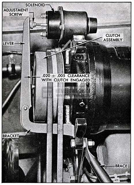
1954 Buick Compressor Clutch
In this engaged position there should be a clearance of .020 +/- .005 between the pin and lever.
The clearance is obtained through adjustment of a nut on the end of the solenoid valve plunger.
NOTE: Make certain the locking nut is secured after the adjustment has been made.
- Compressor Mounts.
There has been no change in the rear compressor mount, however, the front mount is entirely new.
An additional brace is used between the front mount and intake manifold to keep compressor vibration to a minimum.
- Compressor Pressure Data.
The compressor pressure data used in checking proper operation of the air conditioning system has not been changed from 1953. (See BPS Bulletin No. 2.346, dated July 1, 1953).
- Service Procedure.
- New Car Make-Ready.
The “make-ready” procedure for checking the air conditioning system remains the same with the addition of checking proper clearance between the compressor clutch dowel pin and lever when the main control switch is “ON” and the solenoid is energized . (See Item 10 under A)
- One Thousand and Two Thousand Mile Inspections
The 1,000 and 2,000 mile inspections remain the same with the following additions:
- Check the clearance between the compressor clutch dowel pin and lever. (See Item 10 under A) Adjust as necessary.
- Check the condenser and radiator grilles for bugs, leaves, etc. Remove as necessary.
- Cold Weather Operation.
With the addition of the compressor clutch it will not be necessary to remove the compressor belts for Winter Operation.
It is recommended that the Summer-Winter switches located in the outside air intake ducts be positioned to the Winter setting when temperature s remain low enough that operation of the air conditioning unit is not desirable.
- Discontinuance of the Pump Down Procedure.
Due to the deletion of the check valve and shut off valve at the receiver, it will be impossible to “pump down” the system.
Any time it becomes necessary to remove a component from the system (other than the compressor) it will be necessary to discharge the entire amount of Freon and, following replacement of component, evacuate and charge as described in Section 7 of the Buick Air Conditioning Manual.
Leave A Comment
You must be logged in to post a comment.