a. Ball Travel
Immediately after the lifter parts have been cleaned and inspected (See Sections 6 and 7) check the ball travel on Test Fixture J 5095 as follows:
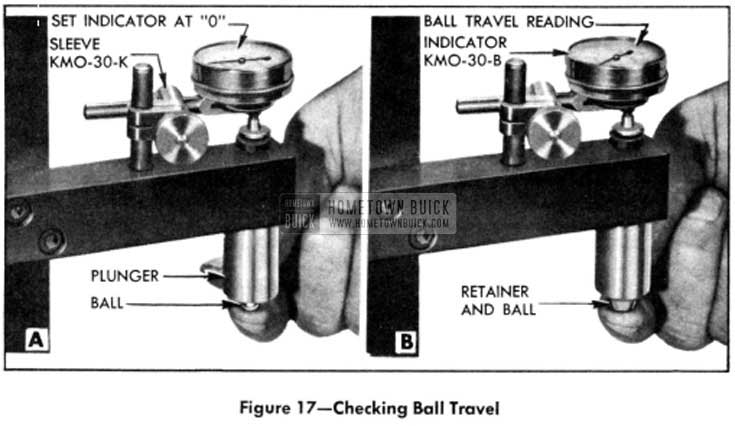
- Use Sleeve KM0-30-K to mount Dial Indicator KM0-30-B so that stem of indicator bears squarely on upper end of the pin in ball travel checking attachment of the test fixture. See Figure 17.
1951 Buick Checking Hydraulic Valve Lifters Ball Travel
- Select a new ball and place it in the seat on plunger, then hold plunger and ball firmly against under side of the attachment arm with plunger centered over the pin and stepped flange. See Figure 17, view A.
- While holding ball and plunger firmly in place, set the dial indicator needle at “0” (zero).
- Remove plunger and ball, place ball in ball retainer, and install these parts on plunger.
- Center the plunger over the pin and stepped flange of the check attachment and while pressing plunger and retainer firmly against attachment arm note the dial indicator reading. See Figure 17, view B.
- The dial indicator reading shows the distance that the ball can travel from its seat until stopped by the retainer. The ball travel must be .004″ to .008″ to insure satisfactory lifter operation.
- If ball travel is not within the specified limits use a new ball retainer and repeat steps 4 and 5. It may be necessary to try several new retainers to select one that provides the required ball travel with the particular plunger and ball.
Too much ball travel will allow more oil to flow from the lifter lower chamber just before the ball seats, causing excess lash in the valve linkage. Insufficient ball travel will cause the volume of oil in the lower chamber to increase or “pump up”, thereby preventing the engine valve from seating
b. Leakdown
After a valve lifter has been cleaned, inspected, checked for ball travel, and assembled it must be tested for leakdown rate before it is installed in an engine. In Section 1, d, leakdown was defined to be the leakage of oil from the lifter lower chamber through the clearance between body and plunger, during opening and closing of the engine valve.
Lifter Test Fixture J-5095 has been designed to test the leakdown rate of a lifter to determine whether it is within limits which assure satisfactory lifter operation. The following procedure must be carefully followed to obtain an accurate test.
- Prepare a special test fluid by placing 12 ounces of SAE 10 engine oil in a CLEAN and accurate one gallon container, fill container to the one gallon mark with kerosene, then stir or shake the container to thoroughly mix the oil and kerosene. NOTE: A Coca-Cola bottle (capacity 6 oz.) makes a convenient measure for the oil. A one gallon glass jug makes a convenient container for the fluid.
- Thoroughly clean the cup of test fixture then set it in place and fill to within 1/2″ of the top.
- Swing the weight arm up out of the way, resting it against the top end of its support.
- Raise the ram and install the valve lifter in the cup of fluid, making sure that it seats squarely on the rubber disc in the recess at bottom of cup. The lifter must be completely covered by the fluid in cup at all times.
- Lower the ram to rest in the lifter push rod seat, then lower the weight arm to rest on the roller of ram.
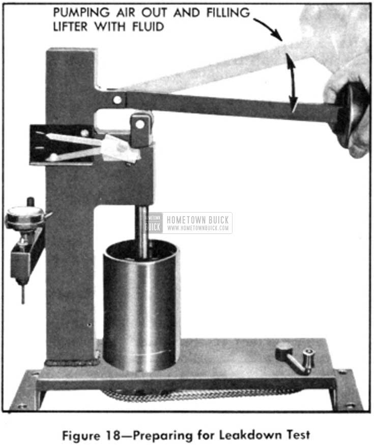
1951 Buick Preparing for Leakdown Test
- Press the weight arm down as far as possible then raise the arm and repeat until consider able resistance is felt. This pumping action will operate the lifter plunger to force air out of lower chamber and replace it with fluid. See Figure 18.
- When resistance has built up, continue pumping until the position of indicator stabilizes itself on the scale. (This is the point w here pointer begins its gradual movement.) Then pump vigorously for approximately 10 strokes or until all air is removed from the lifter. NOTE: If one stroke offers noticeable weak resistance during the last pumping strokes replace the check ball in lifter and repeat the leakdown test to this point.
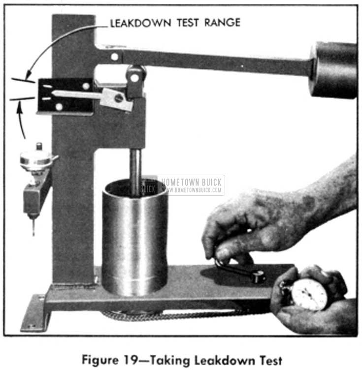
1951 Buick Taking Leakdown Test
- Lower the weight arm to rest on ram roller and as the pointer starts moving upward begin turning the cup by rotating the handle one revolution per two seconds on base of test fixture. See Figure 19. The turning cup rotates the lifter body while the weighted ram holds the lifter plunger from turning, thus averaging out any variations in clearance between these parts. NOTE: Check occasionally to make sure that the plunger is not turning.
- Using a stop watch, note the length of time it takes for the pointer to pass from the lower to the upper mark on the scale. Continue turning the cup during this test. The distance be tween the lower and upper marks indicates the range in which the plunger normally operates in the body.
- The leakdown rate (time for pointer to move from the lower to upper marks) must be between 9 and 38 seconds to assure satisfactory lifter operation. A doubtful lifter should be tested three or four times or until repeat readings are obtained. Discard the lifter if it does not test within the specified limits.
- After all lifters have been tested, place a suitable cover over the test fixture to keep dirt out of the cup and fluid. The fluid should be discarded and the cup should be thoroughly cleaned after a few sets of lifters have been tested.
Leave A Comment
You must be logged in to post a comment.