SECTION 7-D – 1959 BUICK AIR RIDE SUSPENSION
7-18 1959 BUICK AIR RIDE SPECIFICATIONS
Tightening Specifications
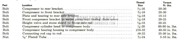
1959 Buick Air Ride Tightening Specifications
Test and Assembly Specifications- General Specifications
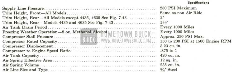
1959 Buick Air Ride Test and Assembly Specifications
Compressor Production Limits & Fits

1959 Buick Air Ride Compressor Production Limits and Fits
1959 Buick Height Control Valve Specifications
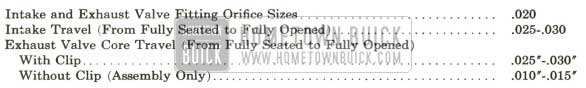
1959 Buick Air Ride Height Control Valve Specifications
7-19 DESCRIPTION AND OPERATION OF 1959 BUICK AIR RIDE SUSPENSION
General Description
1959 Buick Air Ride suspension, available as a factory installed option on all series equipped with power steering utilizes air springs at the rear and low rate coil springs at the front spring location.
An engine driven compressor supplies air at approximately 250 PSI to a storage tank which acts as a reservoir to supply air under pressure to two height control valves, one located at each air spring. Linkage connects the height valves to the rear suspension in such a , manner that weight added to or removed from the chassis will cause air to be added to or removed from the springs to maintain the frame height at a predetermined level.
Air exhausted from the springs is returned through the valve to a tee near the compressor where it is either exhausted inside the 1959 Buick air cleaner or used by the compressor.
All the described operations take place automatically. However, a valve located in the return line enables the operator to shut off the exhaust air when the need for raising the car to change a tire or other service operation arises. With the shut off valve closed, the bumper jack may be used to raise the car without the automatic leveling feature of the height valves in operation.
Compressor
A single cylinder cast aluminum compressor with steel cylinder liner is used. The compressor has a bore of 1 7/8”, a stroke of 1.17″, giving a displacement of 3.23 cubic inches. See Figure 7-23.
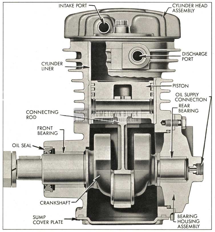
1959 Buick Air Ride Compressor Cutaway
The compressor has a stall pressure, or maximum pressure build up of 250 psi. It is solidly bracketed to the front of the left cylinder head and timing chain cover in position to be belt driven at .875 crankshaft speed by the belt that also drives the power steering oil pump. The compressor cannot be moved to adjust belt tension. Belt tension is adjusted by rotating the power steering pump around its mounting bolts.
A ribbed aluminum cylinder head contains the reed type intake and discharge valves and an intake pipe. The discharge reed valve is assembled to a pressed-in aluminum plate and is not serviceable. The intake valve is assembled over two dowel pins and is replaceable.
A three ring aluminum piston and aluminum connecting rod is used with a full floating piston pin retained by snap rings.
The cast iron crankshaft is supported on two babbitt bearings. The front bearing is pressed into the cylinder crankcase, while the rear bearing is pressed into a bearing housing which bolts to the rear of the compressor body.
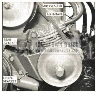
1959 Buick Air Compressor Mounting
Lubrication is provided by engine lubricating oil which is piped from the oil gauge line fitting to the compressor rear bearing housing. The compressor crankshaft is drilled to direct oil to both crankshaft bearings and the connecting rod journal. Oil is retained at the front bearing by a lip type seal on the shaft and at the rear bearing housing by an “O” ring between the bearing housing and the crankcase. The cylinder walls and piston pin are lubricated by splash. Lubricating oil drains down to the bottom of the compressor crankcase where a fitting allows it to drain into a tube leading to a fitting in the engine timing chain cover.
Air Tank
A cylindrical air reservoir tank of 420 cu. in. capacity is bracketed to the front end sheet metal to the right of the radiator core. The tank is pressurized at compressor stall pressure of 250 psi and serves as an air reservoir and water trap.
Air is supplied to the tank from the compressor through a steel tube across the front of the engine where a check valve and connector join it to a tube and flexible hose assembly which attaches to the top of the tank by a flared tube fitting. The check valve prevents loss of air from the tank while the compressor is not running.
The tank outlet fitting is located approximately midway between the top and bottom at the rear of the tank. A Schrader type fitting at the bottom of the tank allows accumulated water to be drained periodically by depressing the valve core.
1959 Buick Air Ride Shut Off Valve
The 1959 Buick air ride shut off valve is located on the radiator mounting panel. The shut off valve is located in the air spring exhaust line and, when closed, prevents air loss from the 1959 Buick air springs. Thus service operations that require lifting the car can safely be performed without loss of air pressure due to height valve operation to trim the car while it is supported by the frame. See Figure 7-22.
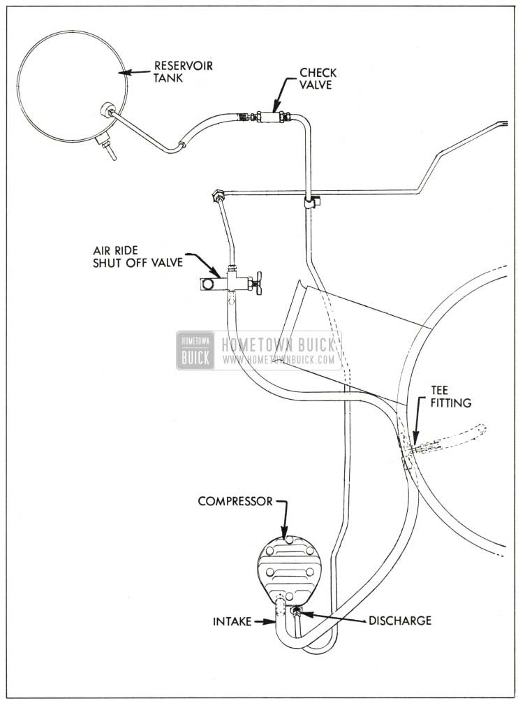
1959 Buick Compressor, Tank and Shut Off Valve Layout
1959 Buick Height Control Valves
- Description
Two height control valves, one for each 1959 Buick air spring, are used. Each height valve is bolted to the frame side rail forward of the rear axle kick up. A lever and link connect the valve to the torque tube strut rod by means of a bracket on the strut rods.
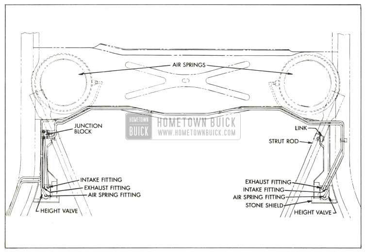
1959 Buick Air Spring and Height Valve Layout
The valves work together to add to, or remove air from the 1959 Buick air springs as weight is added to or removed from the chassis. In this manner the height valves maintain rear trim height at a predetermined level regardless of weight load or level of the ground.
Vertical motion of either rear wheel (in relation to the frame) will move the valve link and lever. The direction of vertical motion will determine whether the valves will cause the 1959 Buick air springs to take in more air or to exhaust air. However, to prevent opening and closing of the valves each time a small bump or series of bumps is encountered, a neutral zone or “dead spot” is built into the valve whereby the axle can move in relation to the frame approximately %” without the valves adding or removing air from the springs. To reduce sensitivity, an orifice is built into both valve intake and exhaust fittings. Thus the compression-rebound cycle of the rear springs, being of short duration, will allow very little air movement during the time the valves are open.
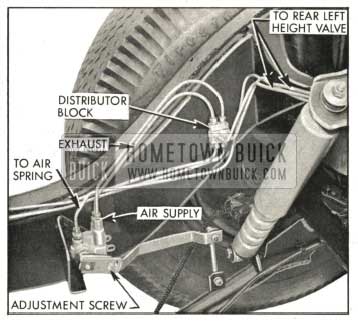
1959 Buick Right Height Control Valve and Lines
A spring loaded over travel device incorporated in each valve lever arm allows lever motion beyond that required to open the valves without damage to the valve mechanism.
- Operation
An air ride car at curb weight will be at correct trim height (within the limits of the valve “dead spot”). When weight is. added, the car lowers and the height control valve arm moves up. A Schrader type valve below the intake fitting is opened mechanically and supply line pressure opens an intake check valve in the intake fitting. Thus both intake valves are open and the exhaust valve closed and air from the reservoir tank will flow to the air spring to lift the car to trim height and close the intake valve.
As weight is removed from the car and the frame raises, the height control valve lever is moved down. A Schrader valve below the exhaust fitting is thus opened to allow air to escape from the spring through the height valve and exhaust lines to a Tee at the engine air cleaner where the air is either exhausted inside the air cleaner or used by the compressor. When sufficient air has been exhausted from the spring, the car will lower to trim height and close the exhaust valve.
1959 Buick Air Springs
1959 Buick air springs are located in the rear of the car in the same position as coil springs on other models. They are dome shaped air chambers consisting of metal containers, into which rubber diaphragms are positioned at the bottom.
The diaphragms are compressed by means of specially shaped plungers between the diaphragms and axle housing. See Figure 7-26.
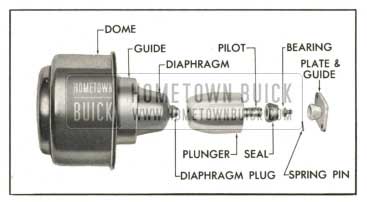
1959 Buick Air Spring Assembly
The domes are stampings with an air fitting welded into the side. The diaphragms are positioned in the domes with diaphragm guides placed up and against the diaphragms. The lip of the dome is crimped over to securely hold the guide in position and form a diaphragm, dome and guide assembly.
Diaphragms cannot be replaced separately. The 1959 Buick air spring dome, diaphragm and diaphragm guide are serviced as one assembly.
Diaphragms are rolling seals made of two ply nylon cord with a layer of natural rubber vulcanized on the inside and a layer of ozone resistant rubber vulcanized to the outside. The spring diaphragms have a bead containing a wire at the outer edge to insure continuous contact with the walls of the dome. The diaphragms are solid at the center and incorporate a plug in their design which centers and holds the diaphragm to the plunger. See Figure 7-27.
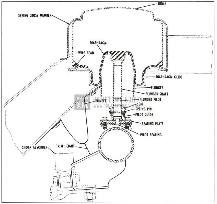
1959 Buick Air Ride Rear Suspension
At the bottom of each plunger a plunger pilot is secured to a pilot guide by a spring pin. The pilot rides on top of a spherical bearing in the pilot guide. A seal is positioned over the guide and pilot to exclude dirt, etc. The bearings handle all angular motion of the 1959 Buick air spring. The bottoms of the pilot bearings fit into a hole in a bearing support plate. The plate itself is bolted to a bracket on the rear axle housing. See Figure 7-26.
The 1959 Buick air spring assemblies are held to the rear spring cross member by two self-tapping screws through retaining clips. A retaining clip is welded at the top of the dome and the screw secures the tang to the cross member. The other clip butts under the dome lip and is secured to the side rail by the screw.
1959 Buick air spring assemblies used on Estate Wagon models are different in size and shape from others and are not interchangeable with them.
The normal pressure within the 1959 Buick air springs is approximately 100 psi. As car weight load is increased, the height control valves allow more air to enter the springs so that trim height remains constant. Pressure within the springs then goes up. The reverse takes place when decreasing load weight.
7-20 1959 BUICK AIR RIDE TROUBLE DIAGNOSIS
Hard Ride Complaint
- Check trim height and correct if necessary.
- Check shock absorbers for proper action and control.
- Inspect rubber bumpers for damage, replace if necessary.
- Check operation of height control valves. See paragraph 7-23.
Car Height Complaint
- Before adjusting height valve position, make sure air ride shut off valve is open.
- If one side of the car will not return to trim height by adjusting the height control valve, that valve is at fault and should be inspected. See paragraph 7-22.
Slow Trimming Complaint
- Check air tank pressure at drain fitting. If pressure is low, make compressor output check as follows :
- Start engine and set speed at 1500 rpm.
- Check air pressure at tank drain fitting, if pressure is above 150 psi, release air till pressure is below 150 psi.
- When pressure in tank builds up to 150 psi start checking compressor. Pressure should rise from 150 psi to 200 psi in 2¥2 minutes or less.
- If pressure does not rise at specified rate, compressor capacity is low. Check for clogged suction hose. Check for leaks in high pressure hoses or fittings if there is no high pressure leak present, remove compressor cylinder head and check intake and exhaust reed valves for proper seating. Replace intake valve if necessary. If exhaust valve is defective, the head and valve assembly must be replaced. If valves are serviceable, compressor must be removed for piston ring replacement and /or general overhaul.
- Check intake and exhaust fittings for plugged orifice or screen.
NOTE: The intake fitting includes a non replaceable intake check valve. If an intake fitting orifice cannot be cleaned with solvent or air blast or if the intake check valve leaks, the fitting assembly must be replaced. See Figure 7-28.
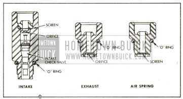
1959 Buick Height Valve Fitting
1959 Buick Air Leak Checking Procedures-Internal
An internal leak is caused either by a leaking exhaust valve core which will allow air to leak out of the height valve, or by a leaking intake valve core which will allow air to leak into the 1959 Buick air spring and cause the car to raise slightly beyond trim height. When the car is lifted higher than trim by a leaking intake core, the normal action of the height valve causes the exhaust valve to be opened, allowing air to escape from the spring thus trimming the car. Repetition of the cycle will lower tank pressure to air spring pressure.
- Check for an internal leak as follows: Make sure air ride shut off valve is open and that car is at trim height with engine not running.
- Disconnect return hose at the fitting and place end of hose in jar of water or use bubble solution to check for flow of air through hose.
NOTE: This must be done without any weight change on car. lf weight is added, such as leaning on a fender, and then removed, height valves will automatically exhaust air.
- If hose does not blow bubbles, there are no internal leaks. Proceed to check for external leaks as outlined in sub-paragraph (e) below.
- If hose blows bubbles, disconnect return line at each exhaust fitting. Use bubble solution at each exhaust fitting. (Exhaust fitting is short fitting next to long intake fitting.) If an exhaust valve core is leaking, height valve must be removed from car for repair and internal adjustment. See paragraph 7-22 (b).
1959 Buick Air Leak Checking Procedures-External
After performing the above procedure and the internal system is free of leaks, check for external leaks by applying bubble solution on all joints and fittings. Correct any leaks found. See note below.
- Check fitting at each 1959 Buick air spring.
- Bubble check air spring diaphragms space between rubber diaphragm and metal diaphragm guide. Check at crimped seam between diaphragm guide and dome. If leak exists, replace 1959 Buick air spring assembly.
- Check all height valve connections; also, cover gasket area and lever pivot shaft.
- Check six connections at junction block to rear of right height control valve.
- Check all reservoir tank fittings.
- Disconnect check valve connector at compressor side of valve. Bubble check disconnected end of valve. If leak exists, replace check valve.
CAUTION: Even after locating an external leak, continue to check points listed as it is possible still another leak exists.
NOTE: All 3/16″ flared tube fittings in the 1959 Buick air ride system are accommodated by a rubber sealing ring in the flared tube seat. ,The sealing ring should be replaced whenever a fitting is disturbed. lf a fitting leaks, the sealing ring should be replaced as a leak can rarely be corrected by tightening the flared tube nut.
1959 BUICK AIR RIDE TROUBLE DIAGNOSIS
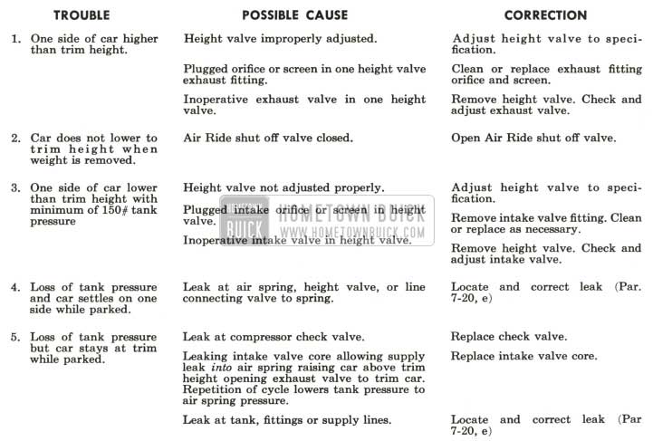
1959 Buick Air Ride Trouble Diagnosis
7-21 REMOVAL AND INSTALLATION OF MAJOR 1959 BUICK AIR RIDE ASSEMBLIES
1959 Buick Air Springs
- Removal
- Jack up car at center of axle housing and place floor stands under frame side rails.
- Lower jack to allow axle housing to come down to full rebound position.
- Disconnect height control valve link at axle strut rod.
- Disconnect air supply line at fitting on air spring being removed.
- Remove two bolts retaining plunger bearing plate to rear axle housing and pull plunger loose from diaphragm center plug. Remove plunger and bearing plate assembly.
- Remove two self-tapping screws at the dome upper and side retainer clips.
- Remove 1959 Buick air spring.
- Replacement
- Reverse steps (d) through (g) used in removal.
- When connecting air line at dome fitting, use new “O” ring.
- Before connecting height valve link to strut rod, raise height valve lever carefully to allow air to inflate assembly.
- Use bubble solution to check air dome fitting for leaks.
- Connect height valve link to strut rod. (f) Jack up rear axle and remove frame support.
Compressor
- Removal
- Loosen belt by moving power steering pump.
- Remove compressor pulley nut, lockwasher, and pulley.
- Disconnect oil supply line at rear bearing support.
- Remove lower of two compressor front bracket to water pump cover and timing chain cover bolts. See Figure 7-23. Loosen top bracket to water pump cover bolt.
- Remove two front bracket to compressor body bolts.
- Disconnect oil return line at compressor body.
- Disconnect compressor intake hose and discharge line at compressor.
- Remove two compressor rear bracket to compressor body bolts. Remove compressor by pivoting front bracket around loose bolt.
- Installation
- Place compressor in position against rear bracket and install two rear bracket to compressor body bolts. Torque to 20 to 30 ft. pounds.
- Attach oil’ supply line to rear bearing housing.
- Attach oil return line to compressor body.
- Connect compressor discharge pipe and intake hose.
- Attach compressor front bracket. Torque two bracket to body bolts to 20-30 ft. pounds and bracket to water pump and timing chain cover to 20-25 ft. pounds.
- Install pulley to engage woodruff key in shaft. Install lockwasher and nut.
- Install belt and adjust to torque specified in Figure 2-37.
- Run engine for a few minutes to check for leaks at oil supply and oil return fittings. Leak test compressor discharge fitting.
1959 Buick Height Valve
- Removal
- Raise car and provide frame support at both rear corners.
- Clean area around height valve and disconnect discharge, exhaust and 1959 Buick air spring lines.
- Disconnect height valve link at height valve arm.
- Remove height valve mounting bolts, height valve and stone shield. See Figure 7-24.
- Installation
- Attach 1959 Buick height valve and stone shield to frame side rail with mounting bolts.
NOTE: It is important to protect the fittings against entry of dirt. - Connect intake, exhaust and 1959 Buick air spring lines to height valve. Use new “O” rings at all fittings.
- Attach height valve link to height valve arm.
- Start engine, remove frame support slowly and allow car to settle on axle bumpers.
- When lift is accomplished, adjust height valve and leak test all height valve fittings.
- Attach 1959 Buick height valve and stone shield to frame side rail with mounting bolts.
7-22 DISASSEMBLY, ASSEMBLY AND ADJUSTMENT – 1959 BUICK AIR RIDE ASSEMBLIES
1959 Buick Air Ride Compressor
- Disassembly
- Remove grease or dirt from the exterior of compressor by using a stiff bristle brush and air hose to prevent dirt from entering the unit. Use Figure 7-30 as a guide during disassembly and assembly.
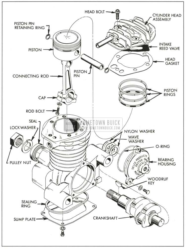
1959 Buick Air Compressor Exploded View
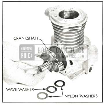
1959 Buick Removing Crankshaft
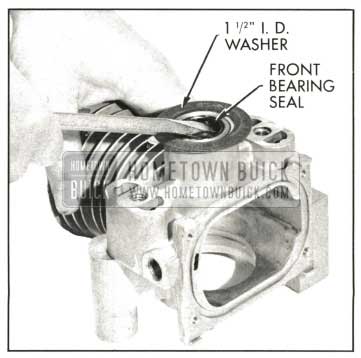
1959 Buick Removing Crankshaft Seal
- Wash all metal compressor parts in a suitable solvent and blow dry with clean dry air. Check all openings and passages to make certain they are open and free from any foreign matter. Examine all bearing surfaces for evidence of excessive wear. Any parts not serviceable should be replaced.
- Inspect bore of front bearing for any digs or scores. Any such damage should be dressed before inserting a new seal.
- Install a new seal using tool #J-7080. See Figure 7-33.
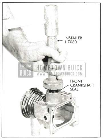
1959 Buick Installing New Crankshaft Seal
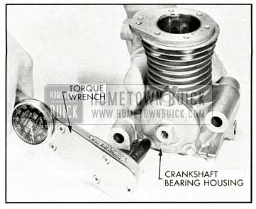
1959 Buick Installing Bearing Housing
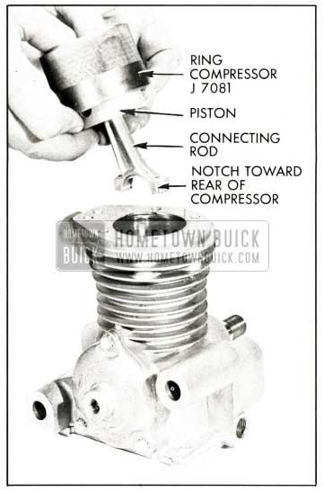
1959 Buick Installing Piston Rod Assembly
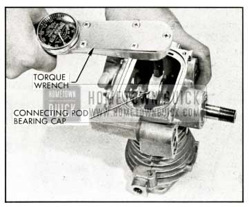
1959 Buick Installing Connecting Rod Bearing Cap
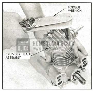
1959 Buick Installing Cylinder Head
1959 Buick Height Control Valves
- Disassembly
- Using a 1/2″ wrench, remove the exhaust, intake and 1959 Buick air spring fittings.
NOTE : The intake fitting is the longer fitting. The exhaust fitting is identified by an orifice in its base, and the 1959 Buick air spring fitting has a screen in its base. Refer to Figure 7-38 as an aid in disassembly and assembly.
- Using a 1/2″ wrench, remove the exhaust, intake and 1959 Buick air spring fittings.
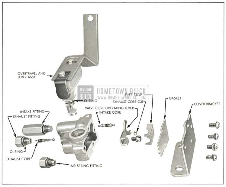
1959 Buick Height Valve Exploded View
- Clean all parts in a suitable solvent. Do not use solvent which will affect rubber since valve core seats are rubber.
- Inspect the intake and exhaust cores. If rubber seats or nylon seals appear damaged, replace the cores. If core stems are bent excessively, replace. If core does not have a positive seating action, replace.
- If any fitting is corroded or rusted internally, replace the fitting.
- Inspect all parts for damage or excessive wear. Replace as necessary.
- Replace piston and spring in bore of overtravel body.
- Lubricate new “O” rings to be used on shaft with silicone grease. Install on shaft.
- Depress the spring loaded piston and install the shaft with the wide untapped flat into the overtravel assembly. Rotate the assembly until piston and spring contacts the flat.
- Reinstall plug in end of overtravel body and metal fastener on overtravel body.
- See Figure 7-39 for identification of cores and install the intake and exhaust cores using Core Remover and Replacer J-6888.
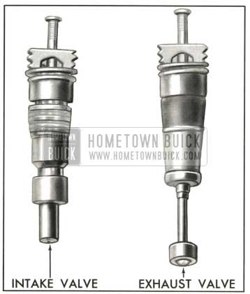
1959 Buick Height Valve Cores
The intake core is installed through the cover side of the valve body. The exhaust core is installed from the fitting side of the valve body. Tighten with finger pressure.
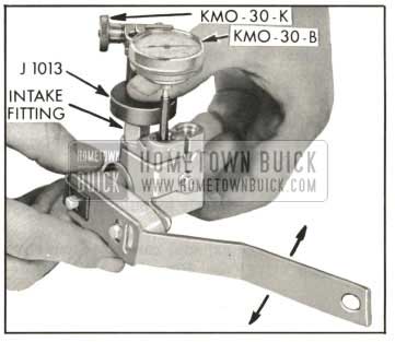
- Mount Dial Indicator, KM0-30-B, Sleeve KM0-30-K and Support J-1013 on the machined cover surface of the valve body. The indicator stem must contact the exhaust core. See Figure 7-40.
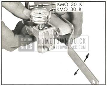
1959 Buick Checking Exhaust Core Travel
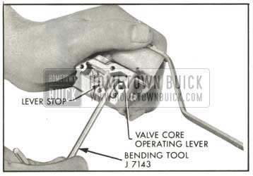
1959 Buick Adjusting Core Travel
1959 Buick Checking Intake Core Travel
7-23 1958 BUICK HEIGHT VALVE ADJUSTMENT ON CAR
- Check the operation of the height control valves by applying weight to each side rear bumper one side at a time. The car should raise back to normal trim height after weight has been added and should lower to trim after weight is removed.
- Check and correct tire pressures and inspect for any binding in the suspension system. Correct if necessary.
- Check 1959 Buick shock absorber action by comparing its action with that of a known good shock absorber.
- Drive the car on a front end alignment rack.
- There is a neutral zone in every height control valve; that is, a dead spot where some movement of the height valve arm is possible without opening either the exhaust or intake valve. To eliminate the variation in trim height caused by this neutral zone, always manually trim the car by pulling down on the frame until air enters the 1959 Buick air spring. Then gradually release the downward pull allowing the car to retrim. This procedure brings the car to trim at the bottom of the height valve dead spot.
- NOTE: The neutral zone or “dead spot” should be between .20″ and .42″ measured at the end of the height valve arm. If the dead spot is out of limits the valve must be removed and adjusted. See paragraph 7-22(b).
- Check the distance between the bottom of the compression bumper and the bumper bracket directly below the bumper. See Figure 7-43.
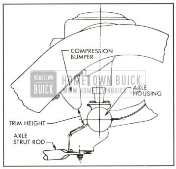
1959 Buick Air Ride Trim Height Measurement
7-24 1959 BUICK AIR RIDE JACK INSTRUCTIONS
When raising an Air Ride car with the bumper jack, it is necessary to close the 1959 Buick air ride shut off valve which is located on the radiator tie bar. The valve is easily accessible when the hood is raised. See Figure 7-44.
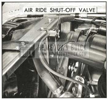
1959 Buick Air Ride Shut Off Valve
If the 1959 Buick air ride shut off valve is not closed before raising the car with a bumper jack. The action of the height control valves may exhaust all the air from the system.
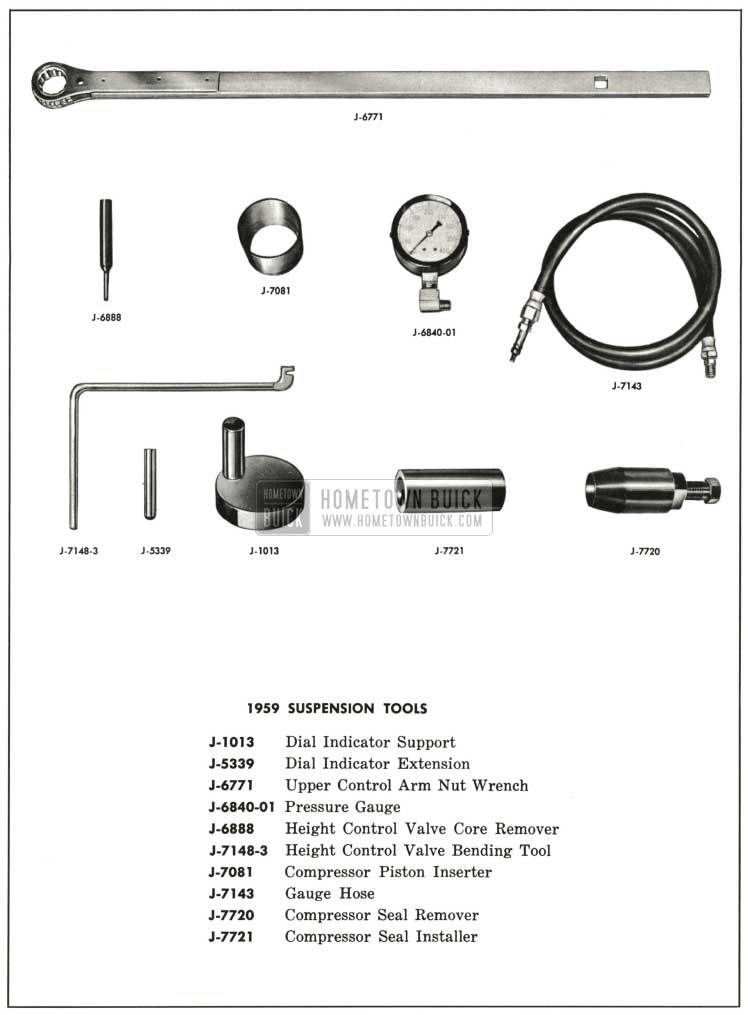
1959 Buick Suspension System Special Tools
Leave A Comment
You must be logged in to post a comment.